

How to Establish a Successful Preventive Maintenance Routine
Maintenance Tips for Ultrasonic Welding Operations
By Mike Gizzi, Global Service and Calibration Manager for Ultrasonics at Emerson
Whether your ultrasonic equipment is brand-new or has been in service for a while, successful preventive maintenance (PM) begins with establishing a maintenance baseline. Basically, that means starting — or continuing — a monthly routine of inspection and maintenance, and recording your results in a maintenance log.
If you’re starting with new equipment, this process is pretty straightforward: You perform the maintenance basics (see below) every two months and record your results in a maintenance log. Try the bi-monthly process for a few cycles, and, if you’re not noting any difficulties, you can make the maintenance interval longer — maybe three months. Eventually, when you note signs or symptoms of wear (see below), you’ll know where to set the interval.
Establishing a baseline
Establishing a baseline for “veteran” equipment is a bit more complicated but every bit as essential. If you’re taking over (or reviving) a maintenance program, begin by consulting any available maintenance logs. Learning the history of your equipment makes the PM process much easier. See what your predecessors have done and how the equipment has performed. Be sure to identify the original weld parameters and stack components for each application (e.g., frequency, amplitude, downforce, energy input, etc.) and see whether they’ve been modified over time.
Modifications to original parameters (e.g., increased weld power or amplitude) or stack components (e.g., booster) can signal past or current maintenance problems. Sometimes, when faced with the need to maintain production, an individual may choose to shortcut maintenance. They might, for example, increase weld amplitude parameters or change to a higher-gain booster in an effort to compensate for aging stack components or a worn-out horn. No welder manufacturer would suggest these or other Band-Aid fixes, but they happen and often result in more costly repairs later.
While the basics of a PM routine don’t change, the timing and intensity of a baseline PM program can vary a great deal based on the application. Think of it this way: Applications that use higher ultrasonic welding frequencies (e.g., 30 kHz or 40 kHz) tend to be “lighter duty” applications, in that they generally weld with lower amplitudes, and less downforce on the weld. Such applications, which are typical in plastic packaging or assembly operations, generally exert lower stress on key welder components — the air cylinder, actuator, and the stack (converter, booster, and horn) — so they tend to cause less wear and tear. By contrast, 15 kHz or 20 kHz welds, which are often used for ultrasonic metal welding, employ lower frequencies and larger horns with greater amplitudes and downforce, so stack component wear — and the likely need for PM — is increased.
Top preventive maintenance concerns
To understand what PM on an ultrasonic welder can do for you, let’s talk about the kinds of problems or failures that you’re trying to prevent and how they occur.
The Stack. The most important maintenance items on an ultrasonic welder are the “stack” components that do the mechanical work: the converter, booster and horn. Each of these components is critical and is carefully selected or custom built (i.e., the horn) to suit a particular welding application. And, although all of these components are engineered with premium materials for maximum durability, remember that each is subjected to stress and wear over millions of cycles. So, occasional maintenance to keep them in top working condition not only prolongs their life but also extends the quality and yield of your welding operations.
At the top of the stack is the converter, which mounts to the actuator assembly located above. This component “converts” electrical energy from the power supply into mechanical energy (frequency/amplitude). The booster, located between the converter and the horn, either “steps up” or reduces the amplitude (vertical motion) of this energy at the frequency needed for the welding application. At the bottom of the stack is the horn, the structure that makes contact with the plastic part. The horn is engineered to transmit the frequency and amplitude of vibration, under downforce pressure from the actuator, to the contours of the part or film. This vibratory energy and downforce are needed to heat the part or film interface and complete the ultrasonic weld.
Making repeatable, reliable plastic welds relies on reliable, repeatable force and energy transfer through the stack to part. The efficiency of that transfer, in turn, relies on the mechanical surfaces and connections within the stack: The converter bolts to the actuator, the booster is torqued to the converter, and the horn is torqued to the booster. Between these mechanical interfaces, there are threaded studs, special washers (e.g., Mylar), or sometimes special greases in the lightest-duty applications.
The actuator and air cylinder
The second most important maintenance items on an ultrasonic welder are in the actuator assembly. In many welders, the actuator assembly includes a pneumatic air cylinder, which supplies downforce, as well as mechanical linkages that hold the stack.
The mechanical linkages within the actuator assembly are engineered to function smoothly for millions and millions of cycles, so the primary PM item is the air cylinder, which relies on the availability of a “clean, dry” air supply. By clean, we mean filtered and contaminant-free (e.g., oil-free), while dry means moisture-free. A clean, dry compressed-air supply is critical because any impurities, such as moisture, oils or particulates, can greatly reduce the life of the piston and seals of the air cylinder. PM practice should include regular inspection of the air supply lines to and within the welder. Any dirt or droplets of moisture or oil indicate a maintenance problem.
Any decline in weld quality is a sure sign that something is wrong. Signals include uneven or incomplete welds, inconsistent weld appearance, uneven wear of the horn, or the perception that the weld process is losing power or needs more power. (Note that a worn anvil or “nest” — the fixture at the base of the welder that holds the lower part of the assembly during welding — could also be a culprit in uneven or inconsistent welds.)
These two items — the stack and the actuator/air cylinder assembly — account for the vast majority of welding problems and therefore ought to be a focus of your preventive maintenance efforts.
PM for the stack
Your welder PM program should aim to keep the entire stack properly tightened, balanced and aligned for maximum performance and life. Normal material wear, loosening or movement, minor misalignments or microfractures (tiny cracks) on any of component surfaces can begin to affect energy transmission through the stack and, therefore, welder performance and product quality and yield. Thus, your PM program should focus in two areas:
- Maintaining proper torque. Stack components usually connect using threaded studs or bolted assemblies that are assembled with a specific level of torque. The stress and vibration of ordinary use can cause these connections to loosen over time. So, it is important to check and re-torque these assemblies periodically.
- Minimizing “fretting” wear on washers or component surfaces. Fretting wear can occur on loaded surfaces, which include, first, the mylar washers that fit between stack components and second, the metal surfaces of the stack components themselves. Fretting happens when minute irregularities on opposing surfaces stick together when compressed but then are repeatedly broken apart by oscillation or slippage, causing loss of surface material and gradual breakdown of the component. As noted, the first surfaces to be affected are the washers that fit between the converter and booster, or the booster and the horn. You can tell a worn washer because it deteriorates into “dirt” on the surface (see Figure 1), while fretted metal surfaces appear as darkened, discolored, or corroded due to the loss or breakdown of certain. (Note: Some light-duty stacks utilize a lubricant instead of a washer in the booster/horn interface.)
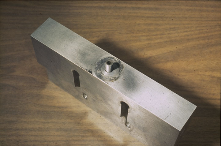
Figure 1: Upon removal and inspection, the top of a weld horn shows a threaded stud, as well as the “dirty” residue left by a worn-out stack washer. Good PM calls for a wipe-down of the surface, installation of a new washer, and re-torquing of the horn/booster interface. Image courtesy of Emerson.
Suggested stack PM:
- Remove stack and inspect at regular intervals (two-three months).
- Disassemble stack and check condition of mylar washer (or lube) on converter/booster/horn interfaces.
- Check for signs of metal fretting or corrosion on converter/booster/horn interfaces and for horn wear.
- Recondition if mild, using factory-recommended procedure.
- Replace converter/booster/horn component if more severe.
- Reassemble:
- Replace mylar washers (or re-lube).
- Reassemble connecting studs/connections.
- Re-torque to specifications.
PM for the air cylinder
By far the two leading causes of air-cylinder problems are oil or water contamination in the air supply, or leaks within the air lines that feed the air cylinder. These problems, or long-term wear, can cause sluggishness in the movement of the actuator, either in downward or upward motion.
Air compressors rely on oil for lubrication, and with age and wear of compressor pistons, oil blow-by increases, enabling oil to get into the compressed air supply. At some point, that oil is going to cause residue or droplets to appear in air supply lines, where it can cause a yellow-brown staining (see Figure 2) and lead to contamination or sealing problems in pneumatic systems.
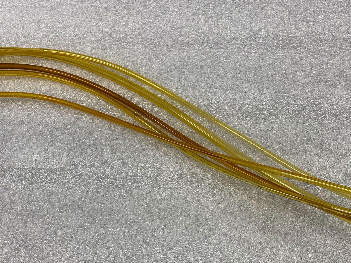
Figure 2: Yellow-brown staining in these air-supply lines means that compressed air is being contaminated by oil blow-by, indicating a worn air compressor or inadequate oil-bleed valve maintenance. Exposure to oil contamination can cause air-cylinder problems that result in poor-quality welds. Image courtesy of Emerson.
Thus, a good PM program should also include installation and maintenance of bleeder valves that capture and contain oil from the compressed air supply. Ultimately, if a significant amount of oil is getting into your pneumatics, or if you see any fine metal particulates, you probably need a new air compressor.
As for moisture problems, consider this: Technical support calls regarding air cylinder problems always spike in the summer months. Customers often state that air cylinders are “sticking,” that solenoids aren’t working properly, or that droplets of oil or water are appearing in the air supply. Such moisture-related problems peak in summer because higher temperatures support higher levels of relative humidity in ambient air. If your facility’s compressed air supply lacks adequate drying capacity, that moisture is going to go into your pneumatic systems, including your welders, and accumulate as water droplets. So, your PM program should periodically evaluate the capacity and performance of your compressed-air drying system.
Suggested PM for the air cylinder and filter:
- Open actuator housing.
- Inspect air lines for presence of oil or water droplets.
- Inspect and clean air cylinder and filter. The air cylinder incorporates a self-draining filter, which should be bled of fluids or dirt on a periodic basis. The filter housing and assembly may also be disassembled and cleaned according to factory instructions, or replaced if it is dirty, wet or leaking.
- Empty oil bleeder valve.
- Maintain compressed-air drying system.
Ordinarily, pneumatic cylinders are so reliable that they rarely need replacement. However, some organizations validate cylinder operation by testing weld force (downforce through the actuator) on a monthly or regular basis. If the value on the welder power supply equals the force value on calibrated test equipment, the cylinder and actuator are operating normally.
PM for the electrical system
The key thing here is visual inspection. Generally, wiring and connections are trouble-free. However, over a period of time, the up-and-down motion of the actuator, which houses the wire bundles that bring power to the converter, can cause fatigue and wear in the wiring. Signs of wear include brown, darkened or cracked areas on wire insulation or on the tubes that carry the wires. Any failure in this area requires factory service.
Conclusion
Broadly speaking, ultrasonic plastic welding is a mature and highly reliable technology. Decades of development have resulted in equipment that combines durable design, advanced digital technology and consistent operation. Because common operating and maintenance challenges are well understood, most welding problems can be prevented or resolved relatively quickly. While this article provides an overview and basic guidelines for understanding and developing a maintenance program, it is not a comprehensive guide. Effective preventive maintenance must always be based on practices and procedures published by the equipment manufacturer.
About the Author
Mike Gizzi is global service and calibration manager for Branson™ ultrasonic plastic and metal welding at Emerson. His 38-year career with Emerson includes 15 years in ultrasonic product electronics, manufacturing and testing, and more than 20 years in managing service and repair operations for Branson ultrasonic cleaning, plastic welding and metal welding equipment, as well as NIST calibration operations for Branson ultrasonic welders used in medical product manufacturing. Learn more at www.emerson.com/branson
Share on Socials!

Why Robotics and Automation are the Perfect Package for Manufacturers
Epson Announces SurePress L-6534VW Digital Label Press
PACK EXPO Returns to Las Vegas
Subscribe!
Sign up to receive our industry publications for FREE!